Wednesday, May 13, 2020

WHAT ARE RHE TYPES OF STRUCTURES ? EXPLAIN JN DETAILS, 2020

TYPES OF STRUCTURES

Structures may be classitied in many ways, based on S1Ze, shape or geometry, support

system, type of material used and methods used in their analysis and design. When a structure
1S subjected to external torces, the elements of the structure are subjected to internal stresses
set in them. the internal stresses and the reaction components can be determined by the
application ot equations oI statics alone, the structure is said to be a staticaly determunate
structure. It however, additional equations, formulated on the basis of consistent deformations
of the elements, are required along with the equations of statics, the structure is Known as
statically ndeterminate srucure.

Depending upon supporting system, structures may be ot three types:

 i)Line strucures having one dimensional supporting system.

ii)Surface structures having the two dimensional supporting system.


(iii) Space structures having three dimensional supporting system.
In the lne structure, having one dimensional supporting system, the structure 1s large in

one dimension in comparison to the other two dimensions. In such a structure, the material
of the element remains concentrated in one line which may be either straight or curved. Flexible
cable is a typical example under this category. A surface structure, which may be either plane
or curved, is large in two dimensions and very small in the third dimension. A surtace structure
may also be composed of a number of continuously connected line structures. The common
examples of surface structures are shell structures (such as water tanks, chimneys, roofs etc.)
having rigid curved surfaces and framed or skeletal structures such as roof trusses, bridge girders
industrial shades etc. Space siructures or three dimensional structures are large in three dimensions.
The common examples of this type are multistoryed buildings, exhibition pavilions, transmission
tower, television masts etc.

Depending upon the shape and geomery, structures may be of three types:
 i)Shell structures
(ü) Framed structures or skeletal structures.
(ü Solid structures.


Saturday, May 9, 2020

How the road patterns are classified ?

    ROAD PATTERNS

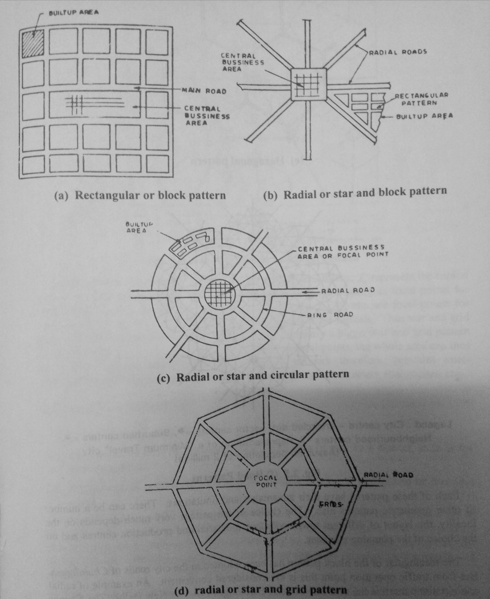
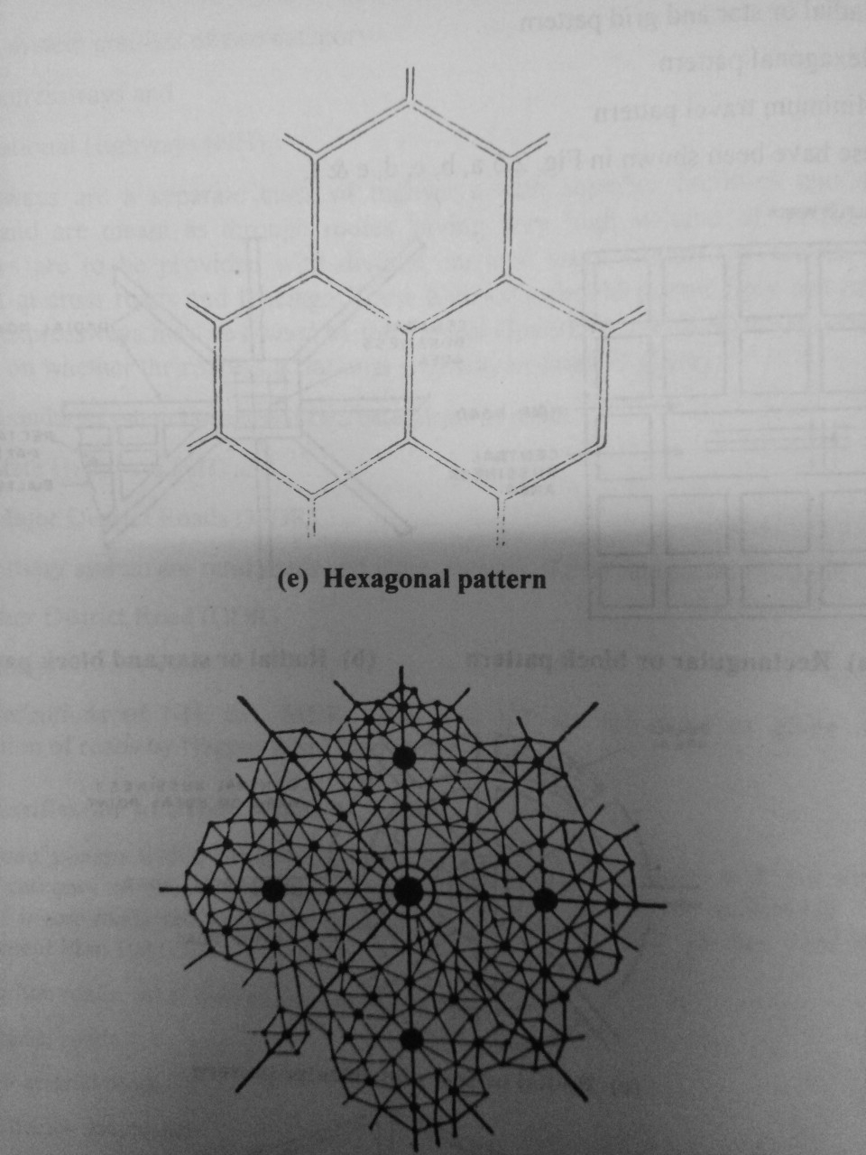
The various road patterns may be classified as follows

(a) Rectangular or block pattern
(b) Radial or star and block pattern
(c) Radial or star and circular pattern
(d) Radial or star and grid pattern
(e) Hexagonal pattern
(f) Minimum travel pattern

These have been shown in Fig. a, b, c, d, e & f.


CLASSIFICATION OF ROADS BASED ON ALL SEASON?

 CLASSIFICATION OF ROADS
   
Types of Roads
           The different types of roads are classified into two categories, depending on whether they can be used during different seasons of the year

  i) All-weather roads and

(ii) Fair-weather roads. All weather roads are those which are negotiable during all weather,except at major river crossings where interruption to traffic is permissible
up to a certain extend.

#Based on the type of the carriage way or the road pavement, the roads are classified as
  
i) paved roads, if they are provided with a hard pavement course which should be
atleast a water bound macadam (WBM) layer and

(ii) unmpaved roads, if they are not provided with a hard pavement course of atleast a WBM layer. Thus earth roads and gravel roads may be called unpaved roads.

#Based on the type of pavement surfacing provided; the road types are divided as:

i)surface roads, which are provided with a bituminous or cement concrete surfacing
and

(ii) unsurfaced roads which are not provided with bituminous or cement concrete surfacing. The roads provided with bituminous surfacing are also called black toped roads.

Nagpur Road Plan classified the roads in India based on location and function into following five
categories and described in section 2.4.3.
 i. National Highways (NH)
(ii) State Highways (SH)
iii) Major District Roads (MDR)
(iv) Other District Roads (ODR) and
(v)Village Roads (VR)


Friday, May 8, 2020

IMPORTANCE OF HIGHWAY DRAINAGE/Significance of Drainage?

IMPORTANCE OF HIGHWAY DRAINAGE

     Significance of Drainage

              An increase in moisture content causes decrease in strength or stability of a soil mass the variation in soil strength with moisture content also depends on the soil type and the mode of stress application. Highway drainage iS l important because of the following reasons

 (i)Excess moisture in soil suberade causes considerable lowering of its stability The pavement is likely to fail due to subgrade failure as discussed in Article 10.1.
(11) Increase in moisture cause reduction in strength of many pavement materials like stabilized soil and water bound macadam.

(1i1)) In some clayey soils variation in moisture content causes considerable variation in volume of subgrade. This sometimes contributes to pavement failure

(iv) One of the most important causes of pavement failure by the formation of waves and corugations in flexible pavements is due to poor drainage.

(v) Sustained contact of water with bituminous pavements causes failures due to
stripping of bitumen from aggregates like loosening or detachment of some of the
bituminous pavement layers and formation of pot holes.

(VI) The prime cause of failures in rigid pavements by mud pumping is due to the
presence of water in fine subgrade soil.

(vii) Excess water on shoulders and pavement edge causes considerable damage.

(viil) Excess moisture causes increase in weight and thus increase in stress and
simultaneous reduction in strength of the soil mass. This is one of the main
reasons of failure of earth slopes and embankment foundations.

(ix) In places where freezing temperatures are prevalent in winter, the presence of
water in the subgrade and a.continuous supplyof water from the ground water can
cause considerable damage to the pavement due in frost action.

(x) Erosion ot soll rom top oF unsurtaced roads and slopes of embankment, cut and
hill side is also due to surface water


Briefly explain the types of Cross Drainage structure?

Cross Drainage

       Whenever streams have to cross the roadway, facility for cross drainage 1s to beprovided. Also often the water from the side drain is taken across by these cross drain in order to divert the water away from the road, to a water course or valley The cross drainage structures commonly in use are culverts and small bridgesWhen a small stream crosses a road with a linear waterway less than about six meter, the cross drainage structure provided is called culvert: for higher values of linear waterway, the structure is called a bridge.

The common types of culverts in use are

     Slab culvert
     Box culvert
     Arch culvert
     Pipe culvert

      slab culverts RcC slab is placed over abutments made of masonry and the span isgenerally limited to 3 metre.
 Box culvert of square or rectangular shapes is mads ofRCC.
 Arch culvert is generaly built using brick or stone masonry, plain cement concrete
may also be used. 
Pipe culverts ot minimum diameter 75 cm and made of steel or prefabricated RCC is used when the discharge is low.

           Various types of bridges are in use: the choice is based on severalconsiderations including the span. RCC and steel bridges are commonly constructed these days

              On less important roads, in order to reduce the construction cost of cross drainage structures, sometimes submersible bridges or cause ways are constructed. During the floods the water will flow over the road. The total period interruption to traffic has however to be kept as low as possible, not exceeding about 15 days in a year.


what are the Requirements of Highway Drainage System?

 Requirements of Highway Drainage System
ans:The followings are the basic Requirements of Highway Drainage System

i) The surtace water from the carriageway and shoulder should effectively be drained off without allowing it to percolate to subgrade

ii) The surface water from the adjoining' land should be prevented from entering the roadway.

(iii) The side drain should have sufficient capacity and longitudinal slope to cary
away all the surface water collected.

(iv) Flow of surface water across the road and shoulders and along slopes should not cause formation of cross ruts or erosion.

(V) Seepage and other sources of under ground water should be drained off by the
subsurface drainage system.

(vi) Highest level of ground water table should be kept well below the level of
Subgrade, preferably by atleast 1.2 m.

(vii) In waterlogged areas special precautions.should be taken, especially if detrimental salts are present or if flooding is likely to occur.


How to Control of Seepage Flow//Control of Capilary Rise??

     Control of Seepage Flow

            When the general ground as well as the impervious strata below are slopping, seepage
flow is likely to exist. If the seepage zone is at depth less than 0.6 to 0.9 metre from the
Subgrade level, longitudinal pipe drain in trench filled with filter materlal and clay seal
may be constructed to intercept the seepage flow. Figure 11.7 shOws the method by
which the seepage line can be lowered to the desired depth.


 Control of Capilary Rise

             If the water reaching the subgrade due to capillary rise is likely to be detrimental, it is
possible to solve the problem by arresting the capillary rise instead of lowering the eater
table. The capillary rise may be checked either by a capillary cut-of of any one of the

following two types

(i) A layer of granular material of suitable, thickness is provided during the
construction of embankment, between the subgrade and the highest level of subsurface
water table, (See Fig. 11.8). The thickness of the granular capillary cut-off layer should
be sufficiently higher than the anticipated capillary rise within the granular layer so that
the capillary water can not rise above the cutoff layer.
(ii) Another method of providing capillary cut-off is by inserting an impermeable or a
bituminous layer in the place of granular blanket. (See Fig. 11.9).


Explain with sketch how the SUB-SURFACE DRAINAGE systemis provided lower the water table?

 SUB-SURFACE DRAINAGE

      Changes in moisture content of subgrade are caused by fluctuations in ground water table seepage tlow, percolation of rain water and movement of capillary water and even water vapour. In sub-surface drainage of highways, it is attempted to keep the variation of moisture in subgrade soil to a minimum. However only the gravitational water 1s
drained by the usual drainage systems.

 Lowering of Water Table
         The highest level of water table should be fairly below the level.of subgrade, in orderbthat the subgrade and pavement layers are not subjected to excessive moisture. From practical considerations it is suggested that the water table should be kept atleast 1.0 to
1.2 m below the subgrade. In places where water table is high (almost at ground level at times) the best remedy is to take the road formation on embankment of height not less than 1.0 to 1.2 metre. When the formation is to be at or below the general ground level, it would be necessary to lower the water table.
             If the soil is relatively permeable, it may be possible to lower the high water table by merely construction of longitudinal drainage trenches with drain pipe and filter sand. The depth of the trench would on the required lowering of water table, distance between the
drainage trenches and soil types. See Fig. 11.5

           If the soil is relatively less permeable, the lowering of the ground water level may not be adequate at the centre of the pavement or in between the two longitudinal drainage trenches. Hence in addition, transeverse drains may have to be provided in order to efectively drain off the water and thus to lower the water table upto the level of transverse drains. A typical sketch of sub-surface drainage system with longitudinal and transverse drains for effective lowering of water table is shown in Fig. 11.6.


Explain Saturation system for Phasing of Road Development Programme?

Saturation system

In this system the optimum road length is calculated for area, based on the concept of obtaining maximum utility per unit length of road. Hence this system is called saturation
system or maximum utility system. The factors which are taken for obtaining the utility
per unit length of road are

(a) Population served by the road network

(b) Productivity served by the net work

         i) Agricultural products

         ii) Industrial products

The following steps may be followed to find the road net work having maximum utility
per unit length by the saturation system.

Step (i) Population units. Since the area under consideration may consist of villages and towns with different populations, it is required to group these into some convenient population ranges and to assign some reasonable values of utility units to each range of
populations served. For example, villages having population range between 1001 and 2000 may be grouped together and be assigned one utility unit per village. Similarly the various villages and towns may be grouped in different population ranges and be assigned
Suitable utility units

Step (ii) Productivity units. The total agricultural and industrial products served by each road system should be worked out. The productivity served may be assigned agricultural products may be considered equivalent to one unit. Similarly the industrial products may also be assigned some suitable utility units per unit weight.However, coal, raw materials like ores etc. may be assigned lower utility values than the industrial products. From plan II showing the products in the area, the total productivity units appropriate values or utility units per unit weight. For example one thousand tonnes of served by each road system may be estimated.

Step (iii) Utility. The total utility units of each road system is found by adding the
population units and productivity units. The total units are divided by the total road
length of each system to obtain the utility rate per unit length.

      Each road system having different layout and length would show different values of utility per unit length. The proposal which gives maximum utility per unit length may be chosen as the final layout with optimum road length, based on maximum utility on the saturation system. This method is useful not only to choose the best layout from the alternate proposals,

but also to phase the road development plan. The only limitation of thè system is the
possible variation in the relative weightages assigned to population and productivity. It is possible to give a relatively higher weightage either to the population or to a certain type of products. A sound judgment based on professional skill and experience should be helpful in providing balanced weightages for arriving at the optimum road length or the best road system with maximum utility per unit length of road.

Phasing of Road Programme
         The road net-work to be constructed and improved in the plan period is decided while finalising the master plan of the road development project. The plan period may be of ablong term, like that of the 20-year road plan or of shorter period like five year plans. But whatever be the plan period, it 1s necessary to phase the road development programme from financial considerations. In other words, it is necessary to fix up the priorities for
the construction of each link of the road net work development programme to decide which link should be taken up first and which one the next and so on. The phasing may also be done for each annual budget year by fixing up the priorities.

         Here again the priority for each road link may be fixed scientifically based on
maximum utility. The utility per unit length of road based on population and productivity for each road is worked out. Then each link or the net work 1S listed in the order of priority based on utility per unit length of the road.


Road Development Plan, Vision 2021/Vision 2025- HIGHWAY ENGINEERING

Road Development Plan, Vision 2021

       Road Development Plan, Vision 2021
i)Half of the national Highway length should have four/ six

ii)10,000 Km of State Highways should have four lanes and

iii)Forty percent of the major Distriet Roads should have
lanes, and the remaining half should have two-lane
and carriageways with hard shoulders..
the balance should have two lanes
two lane carriageways.

iv)The targets for basic access to village should have two
lane carriageways .

v)Maintenance of existing assets should receive adequate
attention .
vi)Research and Development activities in the road Sector
should receive good attention
  #Road Development Plan, Vision 2021

Rural Roads, Vision 2025

i)The Indian Roads Congress Have Prepared a Rural Road Development Plan, Vision 2025 The salient features of the Plan

ii)Master Plans should be Prepared for Rural
Roads showing the core Network which gives
accessibility to each village. All future
programmes should strictly conform to this network

iii)All habitations with a population of above 100 will be connected by all weather roads


Thursday, May 7, 2020

EXPLAIN PLANNING SURVEYS ABOUT HIGHWAY PROJECT

PLANNING SURVEYS about highway project 

Highway planning phase includes

i) Assessment of road length requirement for an area (it may be a district, state or the whole country)

(ii) Preparation of master plan showing the phasing of plan in annual and or five year
plans.

       Thus for assessing the road length requirement, field surveys are to be carried out to collect the data required for determining the length of the road system. The field surveys
thus required for collecting the factual data may be called as planning surveys or fact finding surveys. The planning based on the factual data may be considered scientific and Sound.

The factual studies point to an intelligent approach for planning and these studies
should be carried out if the highway programme is to be protected from inconsistent and short sighted policies.

The planning surveys consist of the following studies; the details 
(a) Economic studies
(b) Financial studies
(c) Traffic or road use studies
(d) Engineering studies


(a) Economic Studies
The various details to be collected are useful in estimating the economics involved in the highway development programme. Hence it is desirable to find the serVice given by each road system to the population and products of the area. All details of the existing facilities should be available before estimating the requirement such that economic
justification can be made for each plan. The details to be collected include the following:

  (i) Population and its distribution in each village, town or other locality with the area
classified in groups.
(ii) Trend of population growth.
(iii) Agricultural and industrial products and their listing in classified groups, area wise.
(iv) Industrial and agricultural development and future trends.

(v)Existing facilities with regard to communication, recreation and education etc.
(vi) Per capita income.

(b) Financial Studies
The financial studies are essential to study the various financial aspects like sources of income and the manner in which funds for the project may be mobilized. The details to be collected include

   i) Sources of income and estimated revenue from taxation on road transport

  ( ii) Living standards

(iii) Resources at local level, toll taxes, vehicle registration and fines.

(iv) Future trends in financial aspects.


(c) Traffic or Road Use Studies
All the details of the existing traffic, their volume and pattern of flow should be knownbelore any mprovement could be planned. Traffic surveys should be caried out in the whole area and on selected routes and locations in order to collect the followlng particulars

(i) Traffic volume in vehicles per day, annual average daily traffic, peak and design hourly traffic volume.

(1i) Origin and destination studies

(iii) Traffic flow patterns

(1V) Mass transportation facilities

(v) Accidents, their cost analysis and causes

(vi) Future trend and growth in traftic volume and goods traftic; trend in traffic pattern

(VI1) Growth of passenger trips and the trend in the choice of modes.

(d) Engineering Studies
All details of the topography, sol and other problems such as drainage, construction
and maintenance problems should be investigated before a scientific plan or programme is Suggested. Ihe studies include
(i) Topographic surveys
 
(11) Soil surveys

(iii) Location and classification of existing roads

(iv) Estimation of possible developments in all aspects due to the proposed highway
development.

(V) Road life studies

(vi) Traffic-studies-Origin and Destination studies

(Vii) Special problems in drainage, construction and maintenance of roads.
      
         Thus all the above studies for collecting the factual data for highway planning are
known as fact finding surveys. The details collected are tabulated and plotted on the
maps ot the area under planning.


DIFFERENT MODES OF TRANSPORTATION//CHARACTERISTICS OF ROAD TRANSPORT

 DIFFERENT MODES OF TRANSPORTATION

Three basic modes of transport are by land, water and air. Land has given scope tor
development of road and rail transport. Water and air have developed waterways and
airways, respectively. The roads or the highways not only include the modern highway
system but also the city streets, feeder roads and village roads, catering for a wide range
of road vehicles and the pedestrians. Railways have been developed both for long
distance transportation and for urban travel. Waterways include oceans, rivers, canals
and lakes for the movement of ships and boats. The aircraft and helicopters use the
airways.

Apart from these major modes of transportation, other modes include pipe lines,
elevators, belt conveyors, cable cars, aerial ropeways and monorails. Pipe lines are used
for the transportation of water, other fluids and even solid particles.

The four major modes of transportation are:
  i) Roadways or highways
(ii) Railways
(iii) Waterways
(iv) Airways

The transportation by air is the fastest among the four modes. Air travel also provides
more comtort apart irom saving in transportation time for the passengers and the goods
between the airports. Transportation by water Is the slowest among the tour modes; but
this mode needs minimum energy to haul unit load through unit distance. The
transportation by water is poSSible between the ports on the sea routes or along the rivers
or canals where inland transportation facilities are available.

The transportation along the railway track could be advantageous by railways between
the stations both for the passengers and goods, particularly for longer distances. 1hese
railway tracks could serve as arteries tor transportation by land and the roads could serve
as feeder system for transportation to the interior parts and to the intermediate localities
between the railway stations. The energy requirement to haul unit load through unit
distance by the railway 1s only a iraction (one fourth to one sixth) of that required by road.
Therefore full advantage of this mode should be taken for the transportation of bulk goods
along land where the railway tacilities are available.

The transportation by road is the only mode which could give maximum service to one
and all. This mode has also the maximum flexibility for travel with reterence to route,
direction, time and speed of travel etc. through any mode of road vehicie. ft is possible to
provide door to door service only by road transport. The other three modes, viz., airways,
waterways and railways have to depend on transportation by roads tor the service to and
from their respective terminals, airports, harbours or stations. ne road net work is
therefore needed not only to serve as feeder system for other modes o uportation and
to supplement them, but also to provIde independent raciny to ro vet by a well
planned net work of roads throughout the country.

covered under Koad En


CHARACTERISTICS OF ROAD TRANSPORT

Is an accepted fact that of all the modes the transportation, road transpot is the
st tO tne people. The passengers and the goods have to be first transportea by road
cacning a railway station or a port or an airport. The road netwOrk alone could

serve the remotest villages of the vast country like ours.

The characteristics of road transport are briefly listed here.

(i) Roads are used by various types of road vehicles, like passenger cars, buses, trucks,
wo and three wheeled automobiles, pedal cycles and animal drawn vehicles. But
raiiway tracks are used only by rail locomotives and wagons, waterways are used

by only ships and boats.

(ii) Road transport requires a relatively small investment for the government. Motor
vehicles are much cheaper than other carriers like rail locomotives and wagons,
water and air carriers. Construction and maintenance of roads is also cheaper than

that of railway tracks, docks, harbours and airports.

(iii) Road transport offers a complete freedom to road users to transfer the vehicle from one lane to another and from one road to another according to the need and convenience. This flexibility of changes in location, direction, speed and timings of travel is not available to other modes of transport.

(iv) In particular for short distance travel, road transport saves time. Trains stop at
junctions and main stations for  comparatively longer time.

(v) Speed of movement is directly related with the severity of accident. The road safety decreases with increasing dispersion in speed. Koad transport is subjected to a high
degree of accidents due to the tlexibility or movements offered to the road users.
Derailment of railway 1ocomouves and air crash of air planes are also not uncommon. 1hey are in ract more disastrous.

(vi) Road transport is the only means or transport that offers itself to the whole
Community alike.
Wednesday, May 6, 2020

Salient Features of Nagpur Road Plan

Salient Features of Nagpur Road Plan

i)The responsibility of construction and malntenance or national highways was

assigned to the central government.

(ii) It was a 20-year plan intended for the period l943-63 aiming to provide for about

two lakh km of surfaced roads and remaining unsurtaced roads, so that when this
target is reached, the total road length of 5, 32, 700 km with a density of about 16
km of road length per 100 sq. km area would be available in the country by the year
1963.

(111) The formulae were based on star and gird pattern of road network. But the existing

irregular pattern of roads and obligatory points not fitting in the geometric pattern
were to be given due consideration.

(iv) The first category roads are meant to provide main grids bringing the farthest points

in developed and agricultural area within 8 km of metal led road. The size of the
gird of this category of road in agricultural area would be 16 km so that the
maximum distance from the centre is 8 km and the average distance of the villages
from metalled road would be less than 3.2 km. In non-agricultural area the size of
the gird is of 64 km sides, the farthest distance from the centre to the metalledd
roads being 32 km. The length of road of this category is governed by the area,
particularly the agricultural area and towns or villages with population greater than
2001.

(V) The second category roads are meant to provide internal road system linking small

villages with first category roads. The road length of second category is worked out
on the basis of villages of diferent population ranges, of population less than 5000.

(vi) An allowance for agricultural and industrial development during the next 20 years

was estimated as 15 percent and this allowance was to be provided while
calculating the road length for both the categories of roads.

(vii) The length of railway tracks in the area was also considered in deciding the length

of first category road. The length of railway track is directly subtracted from the
estimated road length of metalled roads.

The length of various categories of roads as per the target of Nagpur Road Plan of
1943-63 and the road lengths achieved by year 1961 are given in Table 2.4. Though the
achievement of total road length was nigner tnan the plan targets, the lengths of NH and
SH achieved were lesser than the plan targets.


Central Road Research Institute//National Highway Act//Highway Research Board//National Transport Policy Committee

Central Road Research Institute

In the year 1950 the Central Road Research Institute (CRRI) was started at New Delhi
1Or research in various aspect of highway engineering. It may be indicated that one of the
recommendations of Jayakar Committee report was to set up a central organisation Ior
research and dissemination of information.

The CRRI is one of the national laboratories of the Council of Scientific and Industrial
Research: the institute is mainly engaged in applied research and offers technical advice
to state governments and the industries on various problems concerning roads.
National Highway Act

In 1956 the National Highway Act was passed. The main features of the act are:
() the responsibility of development and maintenance of the national highway (NH) to

be provisionally taken by the central government.

(ii) the central government to be empowered to declare any other highway as NH or to

omit any of the existing national highways from the list.

Highway Research Board

The Highway Research Board of the Indian Roads Congress was set up in 1975 With a
is expected to act as a national body for co-ordination and promotion of highway

view to give proper direction and guidance to road research activities in India. T he board

Ihe Highway Research Board (HRB) has recommended suitable financial

research.
allocation of research by central and state governments and has chosen high prioriy
research schemes for being taken up first.

The objective of IRC Highway Research Board are :
(i) To ascertain the nature and extent of research required.
(i) To correlate research information from various organisations in India and abroad

with a view to exchange publications and information on roads.

(iin) To co-ordinate and conduct correlation services.
(iv) To collect and disseminate results on research
(V) To channelise consultative services

There are three technical committees of the HRB for (1) identification, monitoring and
research application (ii) road research evaluation and dissemination and (iii) bridge
research, evaluation and dissemination.

National Transport Policy Committee

The Government of India appointed the National Transport Policy Committee (NTPC)
in the year 1978 to prepare a comprehensive national transport policy for the country for
the next decade or so, keeping in view the objectives and priorities set out in the five year
plans. The NTPC report was made available in the year 1980 and many of the major
recommendations of this report have been accepted by the Government of India. Some of
the important recommendations of the NTPC report relate to the liberalisation of the
transport sector, inclusion of transport in the priority sector, optimal in-er-modal mix
between railway and road transport based on resource-cost consideration and energy
conservation. A number of suggestions were made on the road development, these
include the need to take into account the requirements of roads in rural, hilly and tribal
areas in the next perspective road development plans, strengthening of National Highway
system, increase in funds for the maintenance of roads and to connect all the villages with
all-weather low-cost roads within next twenty years. Separate recommendations were
also made for various factors connected with the development and growth of road
transport by the year 2001.


Indian Roads Congress(IRC)

Indian Roads Congress

At the instance of central government a semi-official technical body known as nan
Roads Congress (uR was tormed in 1934. This, it may be recalled, is one or the mait
recommendations made by the Jayakar Committee. The Indian Roads Congress was
constituted to provide a rorum tor regular pooling of experience and ideas on all maters
affecting the planning, construction and maintenance of roads in India, to recomncn
standard specifications and to provide a platform for the expression of protessiona
opinion on matters relating to Toad engineering including such questions as those o
organisation and aaministration. The IRC has played important role in the formulation O
the three 20-year road development plans in India. Now the Indian Roads Congress a
become an active body of national importance controlling specifications, standardisation
and recommendations on materials, design and construction of roads and bridges
IRC publishes journals, research publications, standards specifications guidelines and
otner speclal publications on various aspect of Highway Engineering The technical
activities or the IRCC are mainly carried out by the Highway research Board and several
committees and subcommittees consisting of experts in each subject. The IRC works in
close collaboration with Roads Wing of the Ministry of Surface Transport, Government

of

India.

Economic depression during the thirties of this century delayed the road development
programmes. During this period the share from the Central Road Fund was almost the
oniy source tor highway financing. During the second world war intensive efforts were
made to develop the road net work essential required for strategic considerations. These
projects were substantially supported by defence services funds.

After the second world war, there was a revolution in respect of automobiles using the
roads in our country and a large number of military vehicles started plying on the roads.
Thus the road development could not cope up with rapid increase in road vehicles and so
the existing roads started deteriorating fast The need for proper highway planning was
urgently felt by this time by the authorities

Motor Vehicle Act
In 1939 the Motor Vehicles Act was brought into effect by Government of India to
regulate the road traffic in the form of traffic laws, ordinances and regulations. The three
phases primarily covered are control of the driver, vehicle ownership and vehicle
operation on roads and in traffic stream. Ihe Motor Vehicle Act has been appended with
several ordinances subsequently. The Motor Vehicles Act has been revised in the year
1988.


what is Central Road Fund(CRF)

Central Road Fund

Based on the authority of a resolution adopted by the Indian Legislature, uc
Koad Fund (C.R.F) was formed on Ist march 1929. The consumers of Petro
charged an extra leavy of 2.64 paisa per litre (then two annas per gallon) of petrol to Duid
ro development fund 20 percent of the annual revenue is to be retainea

as a

eniral Reserve, from which grants are to be given by the Central Government for

cexpenses on the administration of the road fund, road experiments and research
on road and bridge projects of special importance. The balance 80 percent 1s tO De
alloted Dy the Central Government to the various states based on actual petrol

pon

or revenue collected. The accounts of the Central Road Fund are

maintained by the Accountant General of Central Revenues and the control on the
expenditure is exercised by the Roads Wing of Ministry of Transport. Recently the rate
of collection of the levy towards the CRF has been revised in order to augment the
revenue under this fund.


Jayakar Committee and the Recommendations

 Jayakar Committee and the Recommendations

otor vehicles. The

After the first World War, motor vehicles using the roads
a better road network which can carry both bullock cart trai
CxISting roads when not capable to withstand the mixed trafc coeanc A resolution
of oy both Chambers of the Indian Legislature 1927 for the appoinnci

to examine and report on the question of road developnent
Tesponse to the resolution, Indian Road Development committee was appo
government with M.R. Jayakar as Chairman, in 1927,

ne Jayakar Committee submitted its report by the year 1928. The most importaint
i) The road development in the country should be considered as a national interest as
(ii) An extra tax should be levied on petrol from the road users to develop a road

recommendations made by the committee are

this has become beyond the capacity of provincial governments and local bodies.

development fund called Central Road Fund.

(iii) A semi-official technical body should be formed to pool technical know how from
various parts of the country and to act as an advisory body on various aspects of

roads.

iv) A research organisation should be instituted to carry out research and development

work and to be available for consultations.

Most of the recommendations of the Jayakar Committee were accepted by the
government, and the major items were implemented subsequently. The Central Road
Fund was formed by the year 1929, the seml-official technical body called the Indian
Roads Congress was formed in 1954 and tne central Koad Kesearch Institute was started

ni 1950.


NECESSITY OF HIGHWAY PLANNING

NECESSITY OF HIGHWAY PLANNING

In the present era planning is considered as a pre-requisite before attempting any
development programme. This is particularly true for any engneering work, as planning
is the basic requirement for any new project or an expansion programme. Thus highway
planning is also a basic need for highway development. Particularly planning is of great
importance when the funds available are limited whereas the total requirement is much
higher. This is actually the problem in all developing countries like India as the best
utilisation of available funds has to be made in a systematic and planned way.

The objects of highway planning are briefly given below

(i) To plan a road net work for eficient and safe trafic operation, but at minimum
cost. Here the costs of construction, maintenance and renewal of pavement layers

and the vehicle operation costs are to be given due consideration.

(ii) To arrive at the road system and the lengths of different categories of roads which

could provide maximum utility and could be constructed within the available
resources during the plan perod under consideration.

(iii) To fix up date wise priorities for development of each road link based on utility as

the main criterion for phasing the road development programme.

(iv) To plan for future requirements and improvements of roads in view of anticipated

developments.

(V) To work out financing system.


WHAT IS SESMIC REFRECTION METHOD? 2020

Wash Boring

Wash Boring

Wash by tripod and boring pulley. consists a casing pipe usually through a
by driving a Equipment casing of driving used in wash.boring is shown in heavy figure drop 1.4he hammer
to a depth of 1.5 m or3.0 m The casing is then cleaned out holeied supp
of a chopping casing. by
bit fastened to the lower end of the drill rod which is inšerted inside the casing


Waler is forced down through tbe drill nd whicb then emergos out  at a high speed througn the small Tub csing opening, cuttingelhe can water from be hose which and in drill twisledas andd the it is rtI drill they drill iuguin overflows rol pumped is in soil The Various primarily strata slurry nal is cxtcaled raiscd is prUvidcd through the tuough between the bit Tr en raises carrying at top fragmentsof are and
cun sumplers. useful he soil guessed us fronm uixture nd dropped with a
udditionul on swivel huse of the a intu casing suils the or water a meas of the tlowing advancing rale of prngress poviules casing soil joint the drill through ro out is at driven the that botom the drill The  T-connection the annular spacc
u conncction w1th a hole and in ihe slurry indicatjon the of an as hole the rod hole, and the between sunip interval Llowing of
betwcen vut. the progresses, thius chopping uhe or so ucilitating bit Huwever, soil type. sanmples this The taken inethod change with
Advantages:
The
Can use of inexpensive
difficult atud terain. easily
he used in portable handling and dilling cquipnments,

Tuesday, May 5, 2020

WHAT ARE THE OBJECTIVES OF sOIL EXPLORATION , GEOTECHNICAL ENGINEERING/GROUND IMPROVEMENT TECHNIQUE /2020

OBJECTIVES OF sOIL EXPLORATION
Objectives of soil exploration can be listed as follows:
i)to access the general suitability of the site

 ii) to achieve safe and economical design of foundations and temporary works.          

  iii) To know the nature of each stratum and engineering propertIes or the SOlL and rock, which may alfect the designàind mode ôf construction of proposed structure and roundation.

iv) To foresee and provide against dificulties that may arise during construction due to ground
and other local conditions.

v)To find out the sources.of.construction material and selection of sites for disposal of water Surplus material.

 vi) to investigate the occurrence or causes of all natural and manmade changes in conditionsand
the results arising from such changes.

ViI) To ensure the safety of surrounding exIsting structures.

ViIl) lo design for the failed structures
unsafe. or remedial measures for the structures deemed to be
 ix)to locate the ground water leveland possible corroSIve etfectof soil and water on foundation materials
X) To delemine the.solution of  construction problems
any like 
environmental problems. sheeting, dewatering or rock excavation.

CONDITIONS OF EQUILIBRIUM

 CONDITIONS OF EQUILIBRIUM

       According to Newton s law, a particle or body can have no acceleration it there s no restultant force acting on it. Such a body is said to be in a state of equilibrium.
      A Single particle or mass point will obviously be in equilibrium if the resultant of all forces acting on it is zero0.
       A stucture as a whole 1S in a state of static equilibrium when the resuitant o1 al Cxtetid forces actng on it is zero.
       In structral analySis, the use of equilibrium equations which states that the structure or parts of it remain in the  stationary position. Hence, if the entire structure is considered, the reacton
rom tne Support and the loads on the structure should be in static equnoruill.
1ne equations of static equilibrium are as folows: 
        i) The summation of all the forces along any axis (x, y and z) 1s zero.

      ii) the summation of all the moments about any axis (x, y and 2) 1S also Zc0
Or 2D(Iwo dimensional)system with x and y-axis the equations of equilibrium are 
summation of    
     Fx=0 fy =0 and mz,=0
 
     H=0 v=0 and M=0
fOr Dhree dimensional) system withx, y and z-axis the equations of equilibrium are
Conditions of equlibrium of summation of 
 Fx=0 Fy= 0 and Fz=0 which must always be
 My =0 Mx=0 and Mz=0 obey by the complete set
oI forces acting on a structure.
where, Fx 2, and are algebraic sum of the components of all external forces
(applied loads and reactive forces) alongX, y and z-axis respectively.
Fx and Fy are shear forces (tangential forces)
FzAxial forces
Similarly, 2Mx.2 My and 2 Mz
forces are the algebraic
(applied sum
loads of the
and moments
reactive forces) of all
about externa
x, y and z-axis
My and respectively.
My are bending moments
M>Torsional moment

COMPATIBILITY CONDITION// DEGREE OF FREEDOM


COMPATIBILITY CONDITION

     -In addition to the static equilibriunm conditions, it is necessary in any structural analysis that all conditions ot compatibility be satisfied.
     -Compatibility codntions means requirement of continuity, such as in joints where two or more members meet.
     -These conditions refer to continuity of the displacements throughout the structure and are sometimes referred to as conditions of geometry.
    -The members meeting at a joint will'continue to meet at the same joint even after deformation 
takes placCe.
     -At rigid joints or connections between two members the displacement (translations and rotations) of both members must be same.
formulating additional equations.
    - The compatibility conditions will help in
displacement. These equations are related to
 
Note: Compatibility equations deal with
balancing of deformations.
   
 DEGREE OF FREEDOM (DOF)

        Equilibrium condition at joints are expressed  as a set of simultaneous in terms of the joint displacements.
      the  number of  simultaneous 
equations will be the same as the
The number component joint 
displacements involved and is known as DOF

ANALYSIS OFINDETERMINATE STRUCTURES

ANALYSIS OF
INDETERMINATE STRUCTURES

As per the NEW CBCS SYLLABUS
prescribed by VTU for V Sem B.E. Civil Engineering

Also useful for B.Tech

INTRODUCTION
METHOD 

MODULE 1 SLOPE DEFLECTION DISTRIBUTION METHOD

MODULE 2 MOMENT


MODULE 3 KANI'S METHOD

MODULE 4 MATRIX METHOD OF ANALYSIS
(FLEXIBILITY METHOD)
ANALYSIS

MODULE 5 MATRIX METHOOD 


*** Basic formula's & forces

Sunday, May 3, 2020

what is engineering?

what is engineering?
-
Engineering in simple words we can say,that to build something by using unusable things 
or
Engineering is the application of science and math to solve problems. Engineers figure out how things work and find practical uses for scientific discoveries. Scientists and inventors often get the credit for innovations that advance the human condition, but it is engineers who are instrumental in making those innovations available to the world.
In his book, "Disturbing the Universe" (Sloan Foundation, 1981), physicist Freeman Dyson wrote, "A good scientist is a person with original ideas. A good engineer is a person who makes a design that works with as few original ideas as possible. There are no prima donnas in engineering."
💗💗🍟📳

STRUCTURAL DATA